Page 393 - Iscar
P. 393

W                                   Rd°
            HM90 ADCT 1505PDR-CF
            Inserts with 2 Different Cutting                                 l
            Edge Configurations Designed                                  ap
            for Chatter Dampening
                                                                       F   r    S
                                                                                                Recommended
                                                      Dimensions                  Tough 1  Hard
                                                                                                Machining Data       MILLING INSERTS
                                                                                     IC830  IC380  ap    fz
             Designation               W       l      ap      S       r      F                  (mm)    (mm/t)
             HM90 ADCT 1505PDR-CF     9.30   15.70   14.00   6.40    0.80   4.20    •     •   5.00-14.00  0.08-0.15
            • For cutting speed recommendations, see pages 462-498
            For tools, see pages: ADK (210) • F90AD-SFR (179) • HM90 E90AD-15 (25) • HM90 E90AD-CF-15 (25) • HM90 E90AD-M-15 (26) • HM90 F90A-15 (178)
            • SM (219)


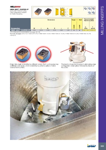
            Edge helix angle is identified by different colors. Each cutting edge has   The inserts should be mounted in alternating edge
            a different axial angle, which is identified by either a yellow or black   configuration order (yellow followed by black) on
            colored flank surface.                                    the cutter.


                                                                                                                  389
   388   389   390   391   392   393   394   395   396   397   398