
Page 325 - Iscar
P. 325
USER GUIDE
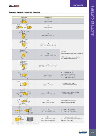
Specially Tailored Inserts for Grooving
Examples Designation
R0.25 TYP.
E1
4.0 GSFP-4.00-0.25 SLOTTING CUTTERS
R1.65 R4.0
E2
3.30 3.95 GSFP-3.95-4.00
1.98
R0.30 R0.05
E3
3.5
GSFP-1.98-0.3-0.05-3.5T
5.28
4.10
R1.2
R0.0 E4A
GSFP-5.28-1.20-0.00-25A4.10
25°
5.28
R0.0 4.10 A–Chamfer
R1.2
E4B Preceding digits: Chamfer angle to center line
GSFP-5.28-25A4.10-0.00-1.20
A–Followed by digits - representing the
25° nominal width location of chamfer
5.28 4.10
2.05
R0.2
R0.0 E5
GSFP-5.28A4.10-0.00-0.20-45A2.05
25° 45°
R0.15 MT – Metric thread 60º
E7 MT – With corner radius
4.4 60°
GIP-4.4-MT-0.15 WT – Whitworth thread 55º
WT – With corner radius
R0.15
E8 V – V shape inclusive angle
5.4 90°
GSFP-5.4-90V0.15 (Blank width 5.4 not rectified)
R0.35 TYP.
E9 K – Frontal straight width of trapezoid
1.82 29° GSFP-4.40-29V1.82K-0.35 (Width 4.40 rectified)
4.4
10°
50° 80° E10 V shape 80º at 10º slant angle
GIP-5.4-80V0.10-10RS (Blank width 5.4 not recitifed)
40°
5.4 R0.1
15°
R0.0
E13 LA – Lead angle - Left-hand
3.10 4.0
GSFP-4.00-0.00-0.30-5LA RA – Lead angle - Right-hand
R0.10 TYP. R0.3
5°
4.5
0.2 E14 T – Depth of groove (nominal)
GIP-1.98-0.00-4.50T0.20B B – Break corners width of chamfers, 45º
1.98 T
GFP-1.98-0.00-4.50T0.20B Note: Blank width > 2B+W
R0.00 TYP.
When ordering inserts, include carbide grade with designation.
321
321