Page 456 - Hartner
P. 456

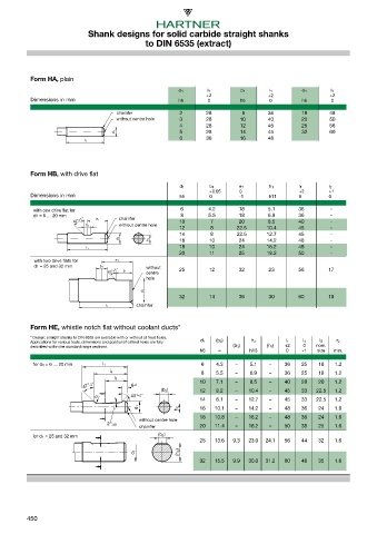
Shank designs for solid carbide straight shanks
                                               to DIN 6535 (extract)


           Form HA, plain

                                                         d 1       l 1       d 1      l 1       d 1       l 1
                                                                  +2                  +2                 +2
           Dimensions in mm                              h6        0         h6       0         h6        0
                                      chamfer             2       28          8       36        18       48
                                      without centre hole   3     28         10       40        20       50
                                                          4       28         12       45        25       56
                                     d 1                  5       28         14       45        32       60
                                                          6       36         16       48
                            l 1

                        45°+1°  e 1
                            b 1
           Form HB, with drive flat
                                      d 1       h 1
                                                          d 1      b 1       e 1      h 1      l 1       l 2
                            l 1      d 1  d 1                      +0.05     0                 +2        +1
           Dimensions in mm                               h6       0         -1       h11      0         0
                            l 1  l 1
                                  e 1
            with one drive flat for   b 1  45°+1°         6        4.2      18        5.1      36        -
            d1 = 6 … 20 mm           l 2                  8        5.5      18        6.9      36        -
                        45°+1° 45°+1° e 1  e 1  chamfer   10       7        20        8.5      40        -
                                                          12       8        22.5     10.4      45        -
                            b 1  b 1   without centre hole
                                           d 1            14       8        22.5     12.7      45        -
                                      d 1  d 1  h 1  h 1  16       10       24       14.2      48        -
                                                          18       10       24       16.2      48        -
                            l 1  l 1 l 1
                                                          20       11       25       18.2      50        -
            with two drive flats for   e 1  e 1
            d1 = 25 and 32 mm  b 1  b 1        without
                                45°+1° 45°+1°  l 2  centre    25   12       32        23       56        17
                                     l 2
                                               hole
                                           d 1  d 1
                                                          32       14       36        30       60        19
                                            chamfer
                               l 1  l 1

           Form HE, whistle notch flat without coolant ducts*
           * Design: straight shanks to DIN 6535 are available with or without oil feed holes.
           Applications for various tools, dimensions and positionof oilfeed holes are fully   d 1   (b2)   h 2   l 1   l4   l 5   r 2
           described within the standard range sections.                   (b3)      (h 3)  +2   0   nom.
                                                                h6    ≈         h13        0    -1   size  min.
           for d 1 = 6 … 20 mm   l 1                             6   4.3   –    5.1   –    36   25    18   1.2
                                                                 8   5.5   –    6.9   –    36   25    18   1.2
                                    l 4
                                     l 5
                                                                10   7.1   –    8.5   –    40   28    20   1.2
                           47° -2°         6 +1
                                                    (b 2 )      12   8.2   –    10.4  –    45   33   22.5  1.2
                               r 2        43° +2°               14   8.1   –    12.7  –    45   33   22.5  1.2
                                            d 1          h 2    16   10.1  –    14.2  –    48   36    24   1.6
                                                                18   10.8  –    16.2  –    48   36    24   1.6
                                             without centre hole
                                             chamfer
                                   2° -30’                      20   11.4  –    18.2  –    50   38    25   1.6
           for d1 = 25 and 32 mm                   (b 3 )
                                                                25   13.6  9.3  23.0  24.1  56  44    32   1.6
                                           d 1           (h 3 )
                                                                32   15.5  9.9  30.0  31.2  60  48    35   1.6


          450
   451   452   453   454   455   456   457   458   459   460   461