
Page 318 - Iscar
P. 318
SLOTTING CUTTERS
W
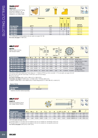
TAG N-UT R 7°
Single-Sided Inserts for Parting,
Grooving & Slitting at Low
Feeds on Cr-Ni Alloys, Ductile
Materials & Low Carbon Steel
Recommended
Dimensions Tough 1 Hard
Machining Data
IC830 IC808 IC908 f groove
Designation W ±0.04 R ±0.04 (mm/rev)
TAG N2UT 2.00 0.20 • • • 0.03-0.10
TAG N3UT 3.00 0.30 • • 0.04-0.12
TAG N4UT 4.00 0.30 • 0.05-0.15
TAG N5UT 5.00 0.30 • 0.05-0.18
TAG N6UT 6.00 0.85 • 0.06-0.22
• For cutting speed recommendations and user guide, see pages 462-468
For tools, see pages: • TGSF (312)
W Da
GM-DG Flange Drive Shank Drive Screw
Slitting Cutters Carrying R (CSI) (SS)
Self-Clamped Inserts D D3
A a°
S/SW-Shank Tmax
Designation W min W max D Z Da A Tmax RPM max a° SS CSI Inserts
GM D100-3DG-22K (1) 2.70 3.35 100.00 6 22.00 2.40 29.00 800 90 SW 32-40 R 22-46 Single-ended:
GM D125-3DG-32K (2) 2.70 3.35 125.00 8 32.00 2.40 34.00 640 0 S 32-55 R 32-55 GIM 3C/3/3J/3.2, GIMY..
GM D160-3DG-32K 2.70 3.35 160.00 10 32.00 2.40 39.00 500 90 S 32-55 R 32-55 Double ended:
GM D200-3DG-40K 2.70 3.35 200.00 14 40.00 2.40 59.00 400 90 S 40-80 R 40-80 for Tmax=12.5mm
GM D100-4DG-22K (1) 3.36 4.35 100.00 6 22.00 3.20 29.00 800 90 SW 32-40 R 22-46 Single-ended:
GM D125-4DG-32K 3.36 4.35 125.00 8 32.00 3.20 34.00 640 0 S 32-55 R 32-55 GIM 4C/4/4J, GIMY..
Double ended:
GM D200-4DG-40K 3.36 4.35 200.00 14 40.00 3.20 59.00 400 90 S 40-80 R 40-80 for Tmax=12.5mm
• D3 refers to SW/S drive shanks and R drive flange set • Maximum RPM may not be exceeded • For user guide, see pages 320-328
(1) Tmax=26 when used with drive flange, D3=46 when used with drive flange
(2) Only one key slot
For inserts, see pages: GIM-C (318) • GIM-J (317) • GIM-W (318)
For holders, see pages: BT-SEMC (908) • C#-SEMC (890) • DIN2080-SEMC (916)
• DIN69871-SEMC (856) • HSK A-SEMC (876) • R (drive flange set) (317) • SMH MB (757) • SW/S (317)
Spare Parts
Designation
GM-DG EDG 44A*
* (Optional, should be ordered separately)
L W
SGSF-W D Lmin Tmax
Grooving and Slitting Cutters
with Integral Weldon Shanks d
A
Lmax
Designation W min W max D d Tmax Z A L min (2) L max (2) L Insert kg
SGSF 32-1.6-W16 1.50 1.79 32.00 16.00 7.00 3 1.32 20.0 49.0 100.00 GSFN/U 1.6 0.135 ESG 1.4-2
SGSF 32-2-W16 (1) 1.80 2.69 32.00 16.00 7.00 3 1.62 20.0 49.0 100.00 GSFN/U 2.0 0.159 ESG 1.4-2
SGSF 40-1.6-W16 1.50 1.79 40.00 16.00 11.00 4 1.32 34.0 63.0 100.00 GSFN/U 1.6 0.158 ESG 1.4-2
SGSF 40-2-W16 (1) 1.80 2.69 40.00 16.00 11.00 4 1.62 34.0 63.0 100.00 GSFN/U 2.0 0.160 ESG 1.4-2
• For user guide, see pages 320-328
(1) Standard GSFN 2.4 mm inserts are not suitable for this tool; for suitable tool, see specific pocket size.
(2) Standard GSFN 2.4 mm inserts are not suitable for this tool; for suitable tool, see specific pocket size
For inserts, see pages: GSFN (319) • GSFU (319)
314 ISCAR