Page 674 - Iscar
P. 674

USER GUIDE
       GUNDRILLS  Typical Gundrill Applications                User Guide


                Main Drilling Methods
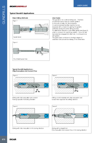
                                                               The gundrill is not a self-centering tool.  Therefore
                Figure 1
                                                               an external means must be used to guide it
                                                               to the point of entry into the workpiece.
                                                               It is recommended that the machine tool be
                                                               equipped with a means for guiding the gundrill,
                                                               preferably during the entire drilling process.
                                                               An alternative method is a pre-drilled guide hole (figure 2),
                                                               which is common for machining centers.  Once the drill
                                                               has been fully engaged into this hole, it continues to be
                                                               self-guided.
                 Guide Barrel                                  The guide pads contribute to the high degree of
                                                               calibration and provide burnishing of the drilled hole.

                Figure 2


                 Pre-Drilled Guide Hole


                Typical Gundrill Applications -
                Chip Evacuation and Coolant Flow

                Figure 3                                       Figure 4


                Boring with chip evacuation and coolant       Drilling of solid material with chip evacuation and
                flowing opposite the boring direction         coolant flow opposite the drilling direction


                Figure 5                                       Figure 6


                Boring with chip evacuation in the boring direction  Boring with a staged tool
                                                              Chip evacuation and coolant flow in the boring direction


   670      ISCAR
   669   670   671   672   673   674   675   676   677   678   679