Page 654 - Iscar
P. 654
GUNDRILLS  TOGT                               Fig. 1     Eh1   R  Wiper  S
                                                                Fig. 2
            Deep Drilling Inserts with 3 Chip
            Splitting Cutting Edges, Positive
            Rake Chipbreaker and a Wiper
                                                                         di


             Designation           di             R           Dimensions        S             Fig.        IC908
                                                                 Eh1
             TOGT 070304-DT        7.69           0.40          1.95           2.30            1         •
             TOGT 080305-DT        8.55           0.50          2.20           2.80            1         •
             TOGT 090305-DT        8.32           0.50          3.00           3.00            2         •
             TOGT 100305-DT        9.23           0.50          3.20           3.30            2         •
             TOGT 110405-DT       10.40           0.50          3.40           3.80            2         •
             TOGT 120405-DT       11.59           0.50          3.60           4.30            2         •
            For tools, see pages: DDD-EF-FT (613) • DSD-EF-FT (604) • DSD-IF-FT (608) • GD-DH (649)


                                                                                            USER GUIDE

                                                                           R

                                             b

                                                        L               h

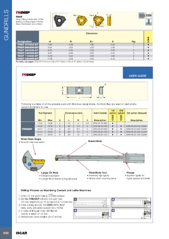
                Following is a table of all the available pads with their new designations, the tools they are used on and priority
                recommendations for use:
                                                                               1st   2nd
                            Tool Diameter      Dimensions (mm)     Solid Carbide  option option 3rd option (brazed)
                                                                                 IC908  IC950
                            Min    Max     b     L      R     h    Description               Description
                            14.00  15.99   5     18     6     2.5  GPS-05-18-060   •
                           16.00   18.00   6     20    7.5    3    GPS-06-20-075    •  •  GPB-06-20-075 CDZAP
                TRIDEEP    18.01   21.00   6     20    8.5    3    GPS-06-20-085    •  •  GPB-06-20-085 CDZAP
                           21.01   25.00   6     20    10     3    GPS-06-20-100    •  •  GPB-06-20-100 CDZAP
                           25.01   28.00   6     20    12     3    GPS-06-20-120    •  •  GPB-06-20-120 CDZAP
                Wide Flute Angle
              • Smooth chip evacuation                         Brazed Body


                              Large Oil Hole                    Steel Body Tool           Flange
                             • Efficient lubrication          • Extremely high rigidity  • Superior rigidity for
                             • Longer life of inserts and guide pads  • Simple direct mounting setup  higher speeds and feeds


                Drilling Process on Machining Centers and Lathe Machines
                                    +0.05
              1. Drill a 15 mm pilot hole D +0.03 flat bottom

              2. Set the TRIDEEP drill into the pilot hole    1                 2
                (10 mm depth).Vc=5-10 m/min f=0.5-1.0 mm/rev
              3. Initial cutting at a 25 mm DOC (80% feed                    15                          10
                rate), verify activated coolant (Vc=100%).
              4. In case of through hole, drill the full   3                    4
                hole to a depth of +5 mm
              5. Retract with slow rotation (5-10 m/min)                      25                    5


   650      ISCAR

