Page 757 - Iscar
P. 757
L3
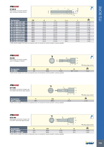
              ST-MB-E                                                         Lmax
              MB Modular Connection System
            with Cylindrical Carbide Shanks             dh6
                                                                       L                                             ITS BORE
                                                                                     CSI

             Designation              CSI          d            L3         L max         L            kg
             ST 16-MB16X110E         MB16         16.00       144.00       100.0        110.00       0.278
             ST 16-MB16X140E         MB16         16.00       174.00       125.0        140.00       0.170
             ST 16-MB16X170E         MB16         16.00       204.00       160.0        170.00       0.420
             ST 20-MB20X135E         MB20         20.00       175.00       125.0        135.00       0.400
             ST 20-MB20X170E         MB20         20.00       210.00       160.0        170.00       0.690
             ST 20-MB20X210E         MB20         20.00       250.00       200.0        210.00       0.400
             ST 25-MB25X160E         MB25         25.00       210.00       160.0        160.00       0.400
             ST 25-MB25X205E         MB25         25.00       255.00       200.0        205.00       1.280
             ST 25-MB25X255E         MB25         25.00       305.00       250.0        255.00       1.555
             ST 32-MB32X195E         MB32         32.00       258.00       200.0        195.00       1.960
             ST 32-MB32X250E         MB32         32.00       313.00       250.0        250.00       2.500
             ST 32-MB32X315E         MB32         32.00       378.00       320.0        315.00       3.300
            • Verify that the weight of the entire tool assembly does not exceed the machine spindle's carrying capability.


                                                           (a)
            R8-MB                                                            SS
            MB Modular Connection System
            with R-8 Bridgeport Shanks                            G1                     CSI

                                                                                    L
                                                                                              (a) Cutting edge position
             Designation               SS             CSI             L              G1             kg
             R8 MB50                   R8             MB50           50.00        UNF 7/16-20       0.840
            • Verify that the weight of the entire tool assembly does not exceed the machine spindle's carrying capability.


                                                          (a)
            MTT-MB                                                       Tt˚
            MB Modular Connection System with
            DIN 228/B 1806 Morse Taper Shanks                                          CSI

                                                                                  L
                                                                                              (a) Cutting edge position
             Designation                 Tt°                CSI                 L                 kg
             MTT 5-MB63                  MT5               MB63                65.00              2.160
            • Verify that the weight of the entire tool assembly does not exceed the machine spindle's carrying capability.


                                                           (a)
            MTD-MB                                                      Tt˚
            MB Modular Connection System with
            DIN 228/A 220 Morse Taper Shanks                    G1                     CSI
                                                                                  L
                                                                                              (a) Cutting edge position

             Designation               Tt°            CSI             L              G1             kg
             MTD 4-MB50                MT4            MB50           63.00           M16            0.928
             MTD 4-MB50 SIP            MT4            MB50           63.00           M14            0.985
            • Verify that the weight of the entire tool assembly does not exceed the machine spindle's carrying capability.


                                                                                                                  753

