
Page 272 - Iscar
P. 272
PLUNGING CUTTERS
ap
HTP-LN06
Side Plungers Carrying Tangentially D d
Clamped Inserts with 4 Cutting Edges
ae
H
L
Designation D ae ap Z H L d Shank (1) kg
HTP D016-2-L120-C16-LN06 16.00 4.5 2.50 2 32.00 120.00 16.00 C 0.166 SR 14-560-HG T-8/53
HTP D020-3-L150-C20-LN06 20.00 5.0 2.50 3 40.00 150.00 20.00 C 0.331 SR 14-560-HG T-8/53
HTP D025-3-L150-C25-LN06 25.00 5.0 2.50 3 50.00 150.00 25.00 C 0.513 SR 14-560-HG T-8/53
HTP D025-4-L130-C25-LN06 25.00 5.0 2.50 4 50.00 130.00 25.00 C 0.439 SR 14-560-HG T-8/53
• For user guide, see pages 272-276
(1) C-Cylindrical
For inserts, see pages: HTP LN.. 0604 (456)
ap T
D Ts D3
HTP-M-LN06
Side Plungers with FLEXFIT Threaded ae
Connection Carrying Tangentially L5 L6
Clamped Inserts with 4 Cutting Edges
Designation D ae ap Z L5 L6 D3 Ts T (1) kg
HTP D16/.62-2-M08-LN06 15.95 4.5 2.50 2 30.00 47.50 13.00 M08 10.0 0.030 SR 14-560-HG T-8/53
HTP D20-3-M10-LN06 20.00 5.0 2.50 3 30.00 50.00 18.00 M10 15.0 0.058 SR 14-560-HG T-8/53
HTP D25/1.00-3-M12-LN06 25.20 5.0 2.50 3 35.00 57.00 21.00 M12 17.0 0.095 SR 14-560-HG T-8/53
• For user guide, see pages 272-276
(1) Clamping wrench size
For inserts, see pages: HTP LN.. 0604 (456)
For holders, see pages: BT-ODP (FLEXFIT) (248) • C#-ODP (FLEXFIT) (248) • CAB M-M (FLEXFIT) (245) • DIN69871-ODP (249) • ER-ODP (249) • HSK A-ODP
(FLEXFIT) (250) • HSK E-ODP (FLEXFIT) (251) • RE MB-ODP (246) • S M (245) • S M-C-H (245) • S M-CF (246)
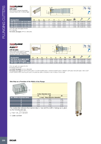
Side Step as a Function of the Width of the Plunge
ae
L1 Cutter Diameter (mm)
16 20 25
ae - Width of plunge (mm) L1 max - Step (effective diameter)
1 7.75 8.72 9.80
2 10.58 12.00 13.56
3 12.49 1428 16.25
4 13.86 16.00 18.33
5 14.83 17.32 20.00
The relationship between the maximal step L1 max and the width of plunge ae is given
by the following formula:
L1 max = 2x D x (ae-ae )
2
D: cutter diameter
268 ISCAR