
Page 262 - Iscar
P. 262
FAST FEED MILLING TOOLS
T Rd°
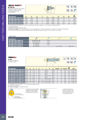
MF EWX-M D Ts
Moderate Feed Endmills with FLEXFIT D1
Threaded Connection Carrying 30°
Double-Sided Inserts with ap
6 Cutting Edges L5
L6
Designation D1 D ap Z L5 L6 Ts T (1) Rd° kg
MF EWX D20-3-M10-04 20.00 13.00 1.50 3 28.00 48.00 M10 14.0 2.4 0.048
MF EWX D25-4-M12-04 25.00 18.00 1.50 4 32.00 54.00 M12 17.0 1.7 0.088
MF EWX D25-3-M12-05 25.00 15.50 2.00 3 30.00 52.00 M12 17.0 3.0 0.074
MF EWX D32-4-M16-05 32.00 22.50 2.00 4 35.00 60.00 M16 24.0 1.9 0.163
MF EWX D32-3-M16-07 32.00 19.70 2.70 3 35.00 60.00 M16 24.0 3.0 0.150
• For machining recommendations and radius for programming, see table on page 446 • For user guide, see pages 462-468
(1) Clamping wrench size
For inserts, see pages: H600 WXCU (446)
For holders, see pages: BT-ODP (FLEXFIT) (248) • C#-ODP (FLEXFIT) (248) • CAB M-M (FLEXFIT) (245) • DIN69871-ODP (249) • ER-ODP (249)
• HSK A-ODP (FLEXFIT) (250) • HSK E-ODP (FLEXFIT) (251) • RE MB-ODP (246) • S M (245) • S M-C-H (245) • S M-CF (246)
Spare Parts
Designation
MF EWX D20-3-M10-04 SR M2.5X6-T7-60 T-7/51
MF EWX D25-4-M12-04 SR M2.5X6-T7-60 T-7/51
MF EWX D25-3-M12-05 SR 10508600 T-9/51
MF EWX D32-4-M16-05 SR 10508600 T-9/51
MF EWX D32-3-M16-07 SR 34-535-SN BLD T15/S7 SW6-T-SH
FF EW D1 D d
Fast Feed Endmills with
FF WOMT... Inserts ap Rd°
D3
L1
H
L
Designation D1 ap D Z H L1 L D3 d Shank (1) Rd° Nxcm (2) kg Insert
FF EW D25-050-W25-06-C 25.00 1.30 11.00 2 53.0 - 118.00 - 25.00 W 5.0 200 0.37 FF WO.. 06
FF EW D25-080-C25-06-C 25.00 1.30 11.00 2 83.0 - 180.00 - 25.00 C 5.0 200 0.58 FF WO.. 06
FF EW D25-080-W25-06-C 25.00 1.30 11.00 2 83.0 - 148.00 - 25.00 W 5.0 200 0.46 FF WO.. 06
FF EW D25-120-C24-06-C 25.00 1.30 11.00 2 121.4 - 220.00 - 24.00 C 5.0 200 0.68 FF WO.. 06
FF EW D32-060-W25-06-C 32.00 1.30 18.00 3 63.0 - 128.00 30.40 25.00 W 4.0 200 0.52 FF WO.. 06
FF EW D32-100-C32-06-C 32.00 1.30 18.00 3 103.0 - 230.00 - 32.00 C 4.0 200 1.28 FF WO.. 06
FF EW D32-100-W25-06-C 32.00 1.30 18.00 3 103.0 - 168.00 30.40 25.00 W 4.0 200 0.73 FF WO.. 06
FF EW D40-100-W32-09-C 40.00 2.00 19.20 3 100.0 97.0 167.50 50.00 32.00 W 5.0 500 1.12 FF WO.. 09
FF EW D40-150-W32-09-C 40.00 2.00 19.20 3 150.0 147.0 217.50 50.00 32.00 W 5.0 500 1.56 FF WO.. 09
FF EW D40-200-W32-09-C 40.00 2.00 19.20 3 200.0 197.0 267.50 50.00 32.00 W 5.0 500 2.00 FF WO.. 09
• For adaptation options, see page • For user guide, see pages 461-468
(1) C-Cylindrical, W-Weldon
For inserts, see pages: FF WOMT/WOCT (445)
Cutting forces are directed axially A cylinder at the bottom of
towards the spindle, enabling the insert provides very rigid
cutting at very high feeds with clamping, absorbing most
high stability and no vibrations. of the forces usually exerted
Ap=2 mm Max on the clamping screw.
for FF WO_T 09T320T
Ap=1.5 mm Max
for FF WOMT 060212T
258 ISCAR